Orifice Plates – Reliable and Cost-Effective Flow Measurement
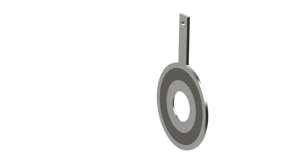
Our Orifice Plates (Models SBA, SBD, PTB, RKB – G, F, JF, JM, T) provide accurate and economical flow measurement for liquids and gases in closed pipelines. They are ideal for clean, non-corrosive media and widely used in power generation, chemical and petrochemical plants, steel and paper mills, and other process industries.
Key Benefits
- Cost-effective standard solution for differential pressure flow measurement
- Suitable for high temperature and high-pressure applications
- Low measurement uncertainty (typically ±0.5% without wet calibration)
- Ideal for high Reynolds numbers
How They Work
Installed between ASME or DIN flanges, the orifice plate creates a defined differential pressure that enables precise mass or volumetric flow calculation. Various designs—concentric, bidirectional, eccentric, or segmental—ensure optimum performance depending on media properties and installation conditions.
Standards & Manufacturing
Flow sizing and design follow ISO 5167-2, ASME MFC-3M, and GOST 8.586-2. Plates are manufactured with strict control of sharp edges, surface finish, and flatness. Thickness typically ranges from 3–10 mm.
Materials & Options
Standard material is 316/316L stainless steel. Other options include Hastelloy, Monel, Titanium, Duplex, and F91.
Available with Raised Face or RTJ sealing surfaces and multiple tapping options (D, D/2, flange/corner taps).
Quality & Services
Manufactured under PED, ASME, IBR, and GOST regulations with a quality system certified to ISO 9001, ISO 14001, OHSAS 18001, and KTA 1401.
Optional services include hydrostatic testing, calibration, corrosion protection, and customized documentation.
Accessories
Complete systems available with valves, condensate pots, thermowells, flow straighteners, additional tappings, and pipe fittings.
Restriction Orifices - Precise Pressure and Flow Limitation
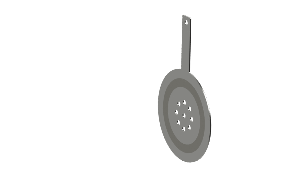
Our Restriction Orifices (Models SBA_RO – J, F, MH, MS) provide a reliable, low-cost solution for limiting pressure or flow in industrial pipelines. They are widely used in power generation, chemical and petrochemical plants, steel and paper mills, and other heavy-process industries.
Key Benefits
- Cost-effective alternative to control valves
- No moving parts – maintenance-free
- Reduced noise and vibration with multi-hole designs
- Increased durability with multi-stage configurations
- Suitable for very high pressure drops in liquid and gas systems
Function & Applications
Restriction Orifices reduce line pressure or restrict flow to a defined value, independent of downstream pressure. They help prevent cavitation, flashing, and critical operating conditions in pumps, headers, heat exchangers, separators, and bypass lines.
They can also be used for controlled pressurization during plant start-up, protecting piping and equipment.
For extreme pressure reduction or noise limitations, multi-hole or multi-stage plates can be installed within a spool piece—improving performance and extending service life.
Unlike measurement orifice plates, restriction orifices have a straight bore (not beveled) to generate higher permanent pressure loss and can operate under sonic/choked flow conditions.
Design & Standards
Sizing is tailored for each application and based on industry standards and tools such as:
CONVAL, R.W. Miller, IEC 60534-8-4, and InstruCalc.
Plates can be installed between flanges or welded directly into the pipeline.
Materials
Standard material: 316/316L stainless steel
Optional materials: Duplex, Hastelloy, Monel, Inconel
Drain and vent holes are available where required.
ISA 1932 Nozzle - High-Accuracy Flow Measurement for High-Velocity Media
Our ISA 1932 Nozzles (Models PTD, RKD, HVD, HEED, HRKD – G, MK, ML, FL) deliver precise and stable flow measurement for high-velocity, non-viscous, and erosive fluids. They are widely used in power generation, chemical and petrochemical plants, steel and paper mills, and other heavy-duty process industries.
Key Benefits
- Excellent long-term stability of the flow coefficient
- Requires shorter straight inlet sections than orifice plates
- Low permanent pressure loss
- Low measurement uncertainty (typical 8%, for β ≤ 0.6)
- Calibrated accuracy down to 15–0.25%
Function & Applications
The ISA 1932 nozzle allows up to 55% higher measurable flow rates than comparable orifice plates. Its smooth, centrical inlet and sharp-edged throat ensure accurate measurement even in high-velocity or erosive service.
Nozzles can be supplied as:
- Weld-in meter runs
- Flange-mounted designs (within bolt circle)
- Versions with annular chambers or single taps
Design & Standards
Flow calculation and design comply with:
- ISO 5167-3
- ASME MFC-3M
All nominal sizes and pipe schedules are available, with dimensional drawings supplied for every nozzle.
Materials
Available in a wide range of materials, including:
Carbon steel, chrome-moly steel, stainless steel, duplex, super duplex, Monel, Hastelloy, and others for special environments.
Quality & Certification
Manufactured under PED, ASME, IBR, and GOST regulations.
Quality system certified to: ISO 9001, ISO 14001, OHSAS 18001, KTA 1401.
Services & Accessories
Optional services include hydrostatic testing, calibration, corrosion protection, and customized documentation packages.
Available accessories: shut-off valves, condensate pots, thermowells, additional tappings, inspection ports, flow straighteners/conditioners, and other pipe fittings.
Long Radius Nozzle - Stable and Efficient Differential Pressure Flow Measurement
Our Long Radius Nozzles (Models HVLD, HEELD, HPLRD – MK, ML, FL, ES) provide highly stable and accurate flow measurement for a wide range of industrial applications, including power generation, chemical and petrochemical plants, steel and paper mills, and other energy-intensive industries.
Key Benefits
- Excellent long-term stability of the flow coefficient
- Shorter required straight inlet pipe lengths
- Lower permanent pressure loss compared to other DP flow elements
- Pressure taps less prone to contamination, ideal for challenging media
Function & Applications
Long Radius Nozzles are typically welded into a meter run and generate a defined differential pressure used to calculate mass or volumetric flow.
They are suitable for clean, high-velocity fluids and are defined in three standard geometries:
- High β nozzle
- Low β nozzle
- Low β nozzle with throat taps
Standard tapping locations:
- Upstream: 1D from nozzle inlet
- Downstream: 5D from inlet or in the throat
Design & Standards
Design and flow calculation comply with:
- ISO 5167-3
- ASME MFC-3M
- ASME PTC 19.5
All nominal sizes and pipe schedules are available. Dimensional drawings are provided for each nozzle.
Materials
Available in a broad selection of materials:
Carbon steel, chrome-moly steel, stainless steel, duplex, super duplex, Monel, Hastelloy, and other alloys for special applications.
Pressure Tappings
The nozzle can include 1 to 4 pairs of pressure taps, with NPT thread, socket weld, or flanged connections.
Quality & Certification
Manufactured in compliance with PED, ASME, IBR, and TR CU regulations.
Quality system certified to: ISO 9001, ISO 14001, OHSAS 18001, KTA 1401.
Services & Accessories
Optional services: hydrostatic testing, laboratory calibration, corrosion protection, and customer-specific documentation.
Available accessories: shut-off valves, condensate pots, thermowells, additional pressure taps, inspection ports, flow straighteners, flow conditioners, and pipe fittings.
Venturi Nozzle - High Accuracy Measurement with Minimal Pressure Loss
Our Venturi Nozzles (Models HVDS, HVDES, HVDSTB, HVDESTB, HRKVDS, HRKVDES, HRKVDSTB, HRKVDESTB – MK, ML, EXT) provide reliable and efficient differential pressure flow measurement for demanding industrial environments. They are widely used in power generation, chemical and petrochemical plants, steel and paper mills, and other energy-intensive industries.
Key Benefits
- Highly stable long-term flow coefficient
- Shorter required straight inlet pipe length than orifice plates
- Lower permanent pressure loss than ISA and long-radius nozzles
- Flow coefficient independent of Reynolds number across the standard range
Ideal for applications requiring high measurement accuracy with minimal energy loss, the Venturi nozzle is suitable for high-velocity, non-viscous, and erosive media.
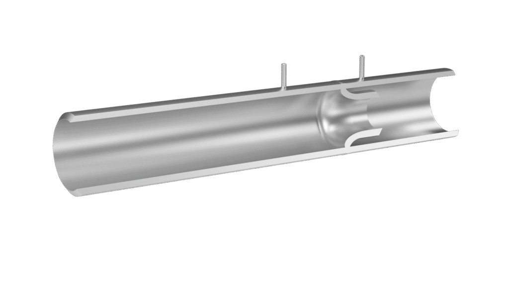
Function & Applications
The Venturi Nozzle (per ISO 5167-3 / ASME MFC-3M) features an axisymmetric design with:
- Rounded convergent section
- Cylindrical throat
- Divergent diffuser section for excellent pressure recovery
This smooth geometry effectively sweeps particles through the device, enhancing durability and reducing wear.
Pressure taps include:
- Upstream corner taps
- Throat taps: at least four single taps connected to an annular chamber
Typical uncertainty of an uncalibrated Venturi nozzle: ±1.5%.
Design & Standards
Design and sizing follow:
- ISO 5167-3
- ASME MFC-3M
All nominal pipe sizes and schedules are available, with detailed dimensional drawings provided for every nozzle.
Materials
Available in a wide range of materials, including:
Carbon steel, chrome-moly steel, stainless steel, duplex, super duplex, Monel, Hastelloy, and special alloys for demanding applications.
Pressure Tappings
Up to 1–4 pairs of tappings, available with NPT thread, socket weld, or various flange connections.
Quality & Certification
Manufactured under PED, ASME, IBR, and GOST regulations.
Quality system certified to: ISO 9001, ISO 14001, OHSAS 18001, KTA 1401.
Services & Accessories
Optional services: hydrostatic testing, laboratory calibration, corrosion protection, and customized documentation.
Accessories include: shut-off valves, condensate pots, thermowells, additional tappings, inspection ports, flow straighteners/conditioners, and various pipe fittings.
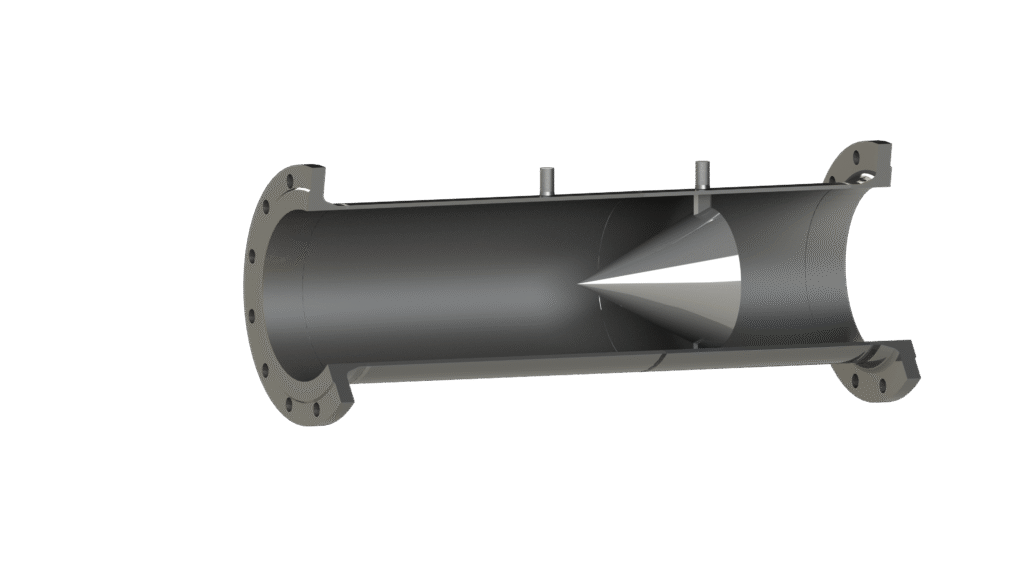
ASME PTC-6 Flow Section - High-Accuracy Flow Measurement for Performance Testing
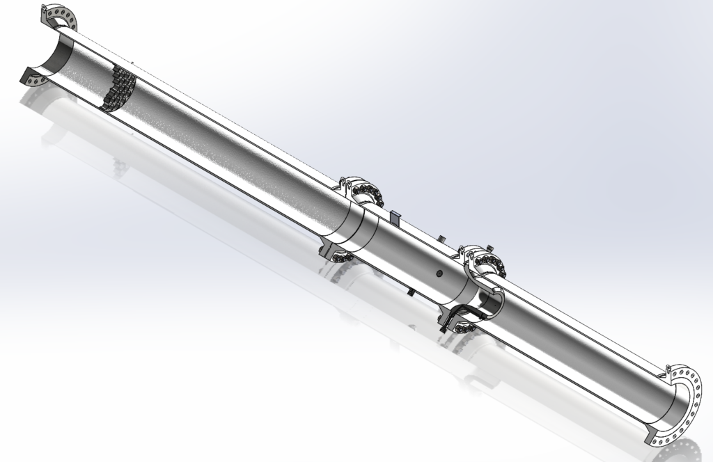
Our ASME PTC-6 flow sections (Models NDPTC_6, HDPTC_6 – ML, FL) are designed for highest-precision flow measurement in demanding power generation environments. They are widely used in fossil and nuclear power plants, industrial steam systems, CHP plants, solar power plants, and other energy-intensive industries.
Key Benefits
- Exceptional accuracy for steam turbine performance tests
- One of the most precise flow devices available
- Delivered only as a fully assembled, calibrated flow section with tube- or perforated-plate flow straightener
- 100% compliant with ASME PTC-6 (2004) dimensional requirements
- Upstream inspection port included
- Mandatory multi-point calibration (minimum 20 points per PTC-6 device)
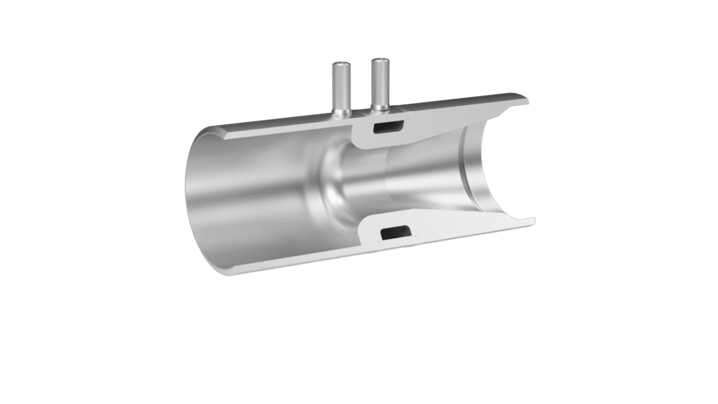
Description
The PTC-6 flow section features:
- Four throat pressure taps
- Beta ratio 0.25–0.50
- Minimum 20D straight inlet pipe, with a flow straightener installed at least 16D upstream of the nozzle
- Flanged assemblies for low-pressure applications (e.g., condensate lines)
- Welded assemblies for high-pressure service, including an upstream inspection port
For applications requiring minimal residual pressure loss, an optional sheet-metal outlet cone can reduce pressure loss by up to 70%.
Design & Standards
Designed according to:
- ASME PTC-6: 2004
- ASME PTC-19.5: 2004 (partially)
Available in all nominal pipe sizes and schedules (recommended range: 4″–28″).
Materials
Manufactured in a wide selection of materials, including:
Carbon steel, chrome-moly steel, stainless steel, duplex, super duplex, Monel, Hastelloy, and special alloys upon request.
Pressure Tappings
- 4 integrally machined throat taps
- Connections via NPT, socket weld, or other specified interfaces
Accessories
Optional equipment includes:
- Single or double shut-off valves
Quality & Certification
Manufactured under SEIKO Flowcontrol’s certified management system:
- ISO 9001
- ISO 14001
- OHSAS 18001
- KTA 1401
Additional Services
Available services include hydrostatic testing, corrosion-protective coating, and customer-specific documentation.
Venturi Tube - High Efficiency, Low-Loss Differential Pressure Flowmeter
Our Venturi tubes (Models HRKVRS, HRKVRES, HRKVREXT, HRKVRTB, VRS, RKVRB, VRB – FL/MK/ML) are designed for precise flow measurement across a wide range of industrial and power-generation applications, including fossil and nuclear plants, industrial steam systems, CHP plants, solar facilities, steel mills, pulp & paper, and chemical/petrochemical processes.
Key Benefits
- Lowest possible permanent pressure loss
- Shortest required straight inlet/outlet lengths
- Excellent wear resistance in dirty or sandy flow conditions
- No moving parts – simple, robust, maintenance-free
- Optional stellite hardening for extreme erosion protection
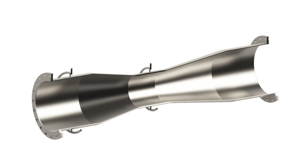
Description
SEIKO Flowcontrol Venturi tubes provide accurate measurement of non-viscous fluids in both clean and contaminated streams. Their angled inlet and outlet cones ensure superior pressure recovery, making the Venturi tube the most efficient differential-pressure device.
The design includes:
- Convergent cone, cylindrical throat, divergent cone
- Optional truncated diffuser (up to 35% reduction with minimal impact on pressure loss)
- Recommended welded construction for large-diameter or low-pressure applications
Upstream tapping is located 0.5D before the convergent cone. Tappings are typically connected via annular chambers and can be supplied with weld ends, threaded ends, or flanges, plus optional condensate pots and shut-off valves.
Typical uncertainties (uncalibrated): 1.0–3.0%.
Permanent pressure loss: 5–10% of differential pressure.
Design & Standards
Designed according to:
- ISO 5167-4
- ASME MFC-3M
- ASME PTC-19.5
Available in all standard pipe sizes and schedules, with customer-specific dimensional drawings.
Materials
Available in: Carbon steel, chrome-moly steel, stainless steel, duplex, super duplex, Monel, Hastelloy, and specialty alloys.
Pressure Tappings
Venturi tubes are built with separate pipe-wall taps connected by annular chambers. All connection types can be provided.
Quality & Certification
Manufactured under SEIKO Flowcontrol’s certified system:
- ISO 9001
- ISO 14001
- OHSAS 18001
- KTA 1401
Certified for PED, ASME, IBR, and GOST.
Services & Accessories
Optional services: hydrostatic testing, laboratory calibration, corrosion protection, and customized documentation.
Accessories include: shut-off valves, condensate pots, thermowells, additional tappings, inspection ports, flow straighteners/conditioners, and various pipe fittings.
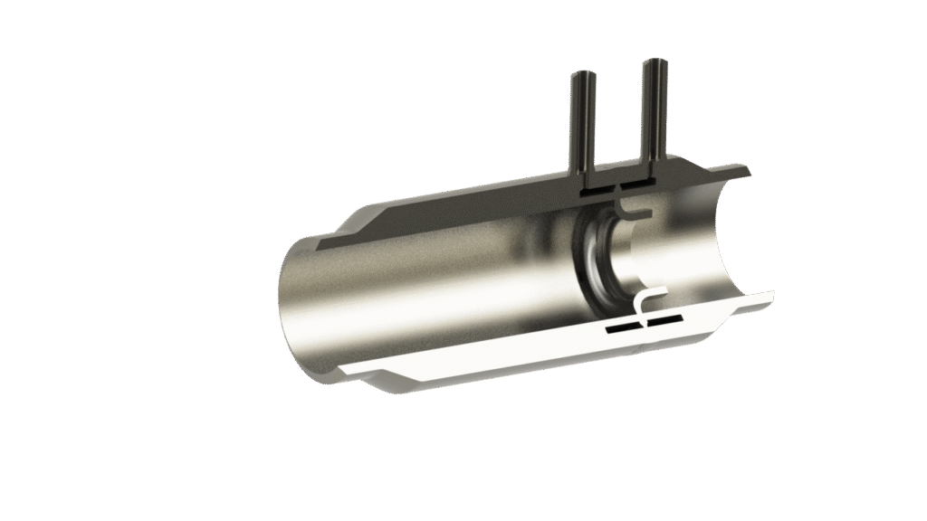
Arrow Bar Pitot Tube – Low-Loss, High-Turndown Flow Measurement
Arrow Bar pitot tubes are widely used across fossil and nuclear power plants, industrial power generation, CHP plants, solar facilities, steel mills, pulp & paper mills, and chemical/petrochemical applications.
Key Benefits
- Very low permanent pressure loss
- High turndown ratio thanks to optimized probe profile
- Suitable for pipe sizes 25 mm to 8000 mm
- Works in round, square, or rectangular ducts
- Low installation and maintenance cost
- Provides long-term accuracy with no moving parts
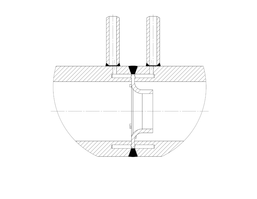
Description
Arrow Bar pitot tubes are inserted through the pipe wall—welded, threaded, or flanged—to measure the differential pressure created by a flowing fluid.
The device features two completely isolated chambers:
- The upstream chamber picks up the impact (total) pressure
- The downstream chamber measures static pressure
The resulting differential pressure is transmitted to a DP transmitter, which outputs a proportional electrical signal for flow calculation.
Connections are typically ½“ or ¾“, available as butt weld, socket weld, threaded, or flanged. Optional condensate chambers and shut-off valves can be provided.
Accuracy of an uncalibrated Arrow Bar pitot tube is typically ~1,5%, provided the required straight upstream and downstream lengths are available.
Nominal Sizes
Available in all standard nominal pipe sizes and schedules.
Customer-specific dimensional drawings are provided for each unit.
Materials
Available in:
Carbon steel, chrome-moly steel, stainless steel, duplex, super duplex, Monel, Hastelloy, and additional special-application alloys.
Quality & Certification
Manufactured in compliance with PED, ASME, IBR, and GOST.
SEIKO Flowcontrol quality system certifications:
- ISO 9001
- ISO 14001
- OHSAS 18001
- KTA 1401
Services & Accessories
Optional services: hydrostatic testing, laboratory calibration, corrosion protection, and customized documentation.
Accessories include: shut-off valves, condensate pots, thermowells, additional tappings, inspection ports, flow straighteners/conditioners, and various pipe fittings.
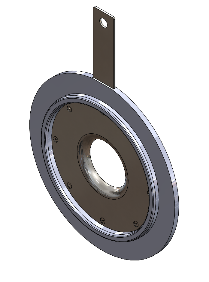
Cone Meter – High-Turndown, Low-Loss Differential Pressure Flowmeter
Upstream tapping is positioned ≥50 mm before the cone, and downstream tapping through the cone is cylindrical and concentric with the cone centerline.
Flow calculation is performed according to ISO 5167-5, with typical uncalibrated uncertainty around 5%. For higher accuracy, full-range calibration over the Reynolds number is recommended.
Design & Standards
- ISO 5167 Part 5
- ASME MFC-3M
All nominal sizes and pipe schedules are available, with dimensional drawings provided for each unit.
Materials
Available in:
Carbon steel, chrome-moly steel, stainless steel, duplex, super duplex, Monel, Hastelloy, and other special alloys.
Pressure Tappings
- Upstream: pipe wall tapping
- Downstream: cylindrical tap through the cone, concentric with the cone axis
- Connections can be butt weld, socket weld, threaded, or flanged, with optional condensate chambers and shut-off valves
Quality & Certification
Manufactured under PED, ASME, IBR, and GOST standards.
SEIKO Flowcontrol quality system certified to:
- ISO 9001
- ISO 14001
- OHSAS 18001
- KTA-1401
Services & Accessories
Optional services: hydrostatic testing, laboratory calibration, corrosion protection, and customized documentation.
Accessories include: shut-off valves, condensate pots, thermowells, additional tappings, inspection ports, flow straighteners/conditioners, and various pipe fittings.
Wedge Meter – Reliable Measurement for Slurries and Dirty Fluids
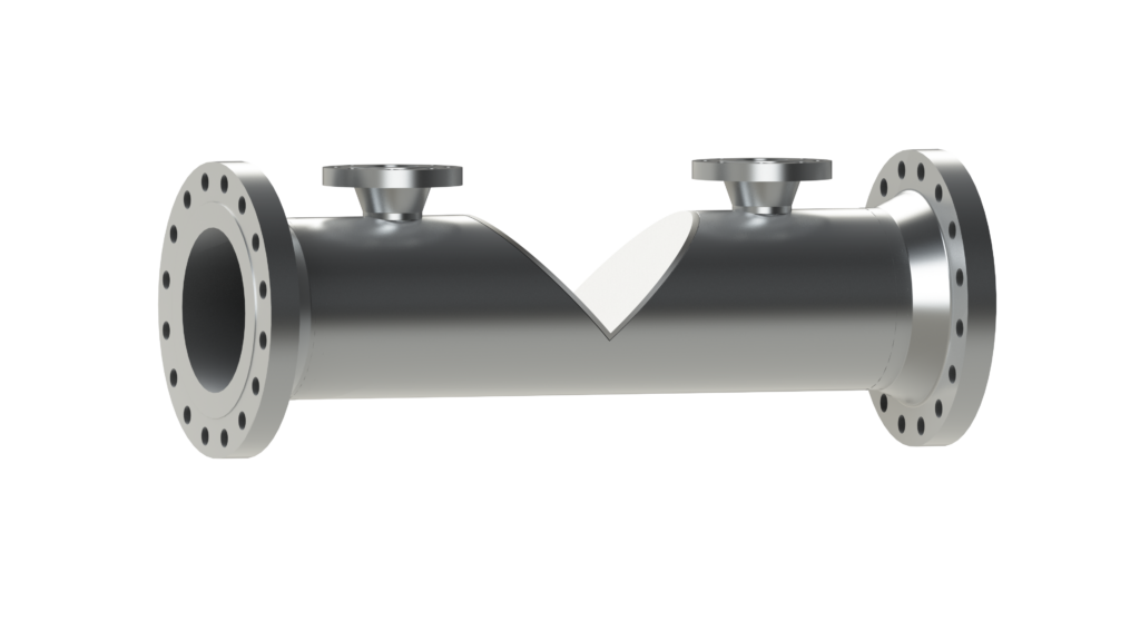
SEIKO Wedge Meters are designed for challenging flow applications in fossil and nuclear power plants, industrial facilities, CHP plants, solar power systems, steel and pulp & paper mills, chemical and petrochemical industries, and other primary energy sectors.
Key Benefits
- Suitable for high-density, slurry, and dirty service
- Operates at very low Reynolds numbers (as low as Re 500)
- V-shaped restriction avoids critical edges, minimizing wear impact and maintaining stable measurement
- Solids pass freely through the restriction without clogging
- Supports bi-directional measurement of liquids, gas, and steam
- Optional large-bore pressure taps for high-viscosity fluids
- Uncalibrated uncertainty ±5%, can be reduced to 25% with laboratory calibration
Description
The Wedge Meter produces a differential pressure via a robust V-shaped restriction. Its durable design makes it ideal for abrasive, viscous, or slurry flows. It ensures accurate flow measurement even under extreme conditions and allows for bidirectional operation.
Materials & Sizes
- Standard: 304SS, 316SS, 316L SS, Carbon Steel
- Special materials available for demanding applications
- Pipe sizes: 5″ to 24″
Quality & Certification
Manufactured in compliance with PED, ASME, IBR, and GOST standards.
Certified to:
- ISO 9001
- ISO 14001
- OHSAS 18001
- KTA-1401
Additional Services
Optional services include hydrostatic testing, laboratory calibration, corrosion protection, and customer-specific documentation.
Quarter Circle Nozzles – Precision Flow Measurement for Low Reynolds Numbers
Our Quarter Circle nozzles (Model Types SQA, MFAQ, PTQ, RKQD, HVQD, HEEQD, HRKQD, G, F, J, T, MK, ML, FL) are engineered for highly accurate flow measurement in demanding industrial environments. Designed for pipelines running completely full, these nozzles create a defined pressure differential between the upstream section and the throat, enabling precise determination of mass or volumetric flow rates.
Special Features & Advantages
Unlike standard orifices or flow nozzles, Quarter Circle nozzles maintain nearly constant discharge coefficients even at very low Reynolds numbers (down to ReD = 500). This stability results from the unique quarter-circle throat geometry, making the nozzle particularly suitable for viscous media such as oils.
Product Description
- Installed in closed pipelines via welding or flanging in a meter run
- Generates a pressure differential used to calculate flow based on nozzle geometry and fluid properties
- Especially effective for low-Reynolds-number applications
- Pressure taps available as corner taps with annular chambers, single taps, or flange taps
- Manufactured from a wide range of materials while maintaining strict adherence to international standards
- Fully defined in global sizing, design, installation, and operational standards
Design & Quality Standards
Manufactured under internationally recognized certifications:
- PED, ASME, IBR, GOST
- Quality system based on:
- EN ISO 9001:2008
- EN ISO 14001:2004
- OHSAS 8001:2007
- KTA-1401
Services & Accessories
Optional services: hydrostatic testing, laboratory calibration, corrosion protection, and customized documentation.
Accessories include: shut-off valves, condensate pots, thermowells, additional tappings, inspection ports, flow straighteners/conditioners, and various pipe fittings.
Flow Conditioners and Straighteners
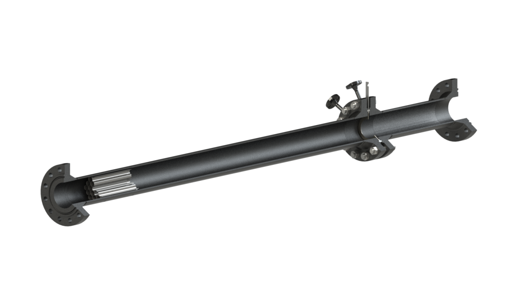
Flow conditioners can be classified as true flow conditioners or flow straighteners. Depending on the type and design, they can be welded or flanged into the pipeline.
Flow Straighteners
Flow straighteners remove or significantly reduce swirl but may not produce a fully developed flow profile. The most common type is the Tube-Bundle Straightener, which consists of multiple parallel tubes fixed together. Other designs are referenced in international standards.
Flow Conditioners
Flow conditioners not only reduce swirl but also redistribute the velocity profile to create conditions close to an undisturbed, fully developed flow profile. Many include or are based on a perforated plate, though a variety of other designs exist.
Materials
Both flow conditioners and straighteners are available in a wide range of materials to suit different applications.
Standards & Installation
Design guidelines, pressure loss calculation, and proper installation procedures are defined in international standards.